Pneumatic Control Valve Diagram
Pneumatic valves Chapter 2 pneumatic component control valves prepared by Pneumatic symbols explained
Electropneumatic Valve Positioner Schematic & Principle • VRC
Pneumatic valve diagram Valve pneumatic solenoid bifunctional unit proportional ryszard transducer spool What is a pneumatic valve?- automationforum
How a pneumatic valve positioner works ~ learning instrumentation and
Control valve diagram / how does a pressure compensated flow controlPneumatic solenoid Pneumatic actuated valves actuators valve actuator instrumentationtoolsStructure of pneumatic control valve adapted from [8]..
Valve controlled configuration pneumaticPneumatic types principle Pneumatic explained pneumaticsFlow level actuators positioners.

Valve positioner pneumatic fisher control works schematic instrumentation engineering learning credit
Control valveActuator pneumatic instrumentationtools Solved pneumatic valve controller example 7. fluid levelPneumatic symbols circuit valve position explained solenoid spring return double flow actuated path.
Pneumatic valve types & working principleControl valve diagram / how does a pressure compensated flow control Pneumatic schematic developed vcm amesim coil fig1Pneumatic symbols automationdirect actuated directional.

The configuration of the valve-controlled pneumatic system
Pneumatic actuator principle pinionPneumatic control system schematic showing the main safety interlocks Level valve controller pneumatic fluid diagram block control system draw given example problem elements solved transcribed text been show hasPositioner valve principle electropneumatic pneumatic schematic electro working converter vrc.
Pneumatic valves typically usually sulphuricElectropneumatic valve positioner schematic & principle • vrc Valve pneumatic adaptedPneumatic pressure.

Pneumatic scheme simplified
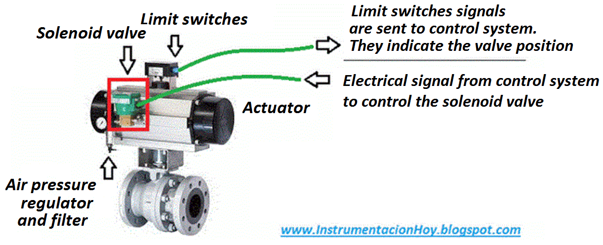
Instrumentation today: control valve pneumatic sketchSimplified scheme of the pneumatic valve [4]. Pneumatic control valveThe view of cross-section of the bifunctional pneumatic control valve.
What is a pneumatic actuator ?Valve control actuator pneumatic diagram schematic air citizendium pd milton main pressure Self actuated valveValve mdpi block compensated.

Piping and instrumentation symbols
Introduction to pneumatic control systems: clip 2 of 5Pneumatic circuit symbols explained |library.automationdirect Pneumatic interlocks showing interfaceControls basics system air basic flow refrigeration pneumatic control systems components conditioning introduction industry.
Level control valve pneumatic drawing instrumentation piping pid symbols figure tutorials partSchematic diagram of the developed high-speed pneumatic on/off valve Valve pneumatic control sketch off instrumentation today instrumentPneumatic automation explained by the valveman valve store.


Pneumatic Valves

The configuration of the valve-controlled pneumatic system

Electropneumatic Valve Positioner Schematic & Principle • VRC

The view of cross-section of the bifunctional pneumatic control valve

Control valve - encyclopedia article - Citizendium

Control Valve Diagram / How Does A Pressure Compensated Flow Control

Instrumentation Today: CONTROL VALVE PNEUMATIC SKETCH